Schuyler McElrath, JASC New Product Development / Technical Sales
“The bitterness of poor quality remains
long after the sweetness of low price is forgotten.”
Benjamin Franklin
Gas Turbine Operational Goals
Reliability from C.I. to C.I. / Reduction of Annual Fuel Costs
Operational/Performance goals for gas turbines are the same regardless of which OEM manufactures the equipment: Liquid Fuel System Reliability.
Similarity of fuel system supply concepts and components make JASC equipment readily applicable for a wide variety of turbine makes and models.
JASC valves have demonstrated the ability to allow customers to transfer seamlessly from gas to liquid fuel with no degradation in reliability between major turbine service intervals.
Additional benefits include:
- Liquid fuel system upgrades which allow valve service at intervals which coincide with those of the turbine without degrading system reliability.
- Operate on gas fuel with monthly, quarterly or annual intervals between liquid fuel operation without impacting turbine start or transfer capability.
- Eliminate forced outages from fuel leaks associated with o-ring failures by incorporating metal to metal sealing on fittings.
How Do We Achieve These Current and Future Objectives?
Provide equally reliable hardware for supporting systems such as purge air and water injection in order to eliminate both trips and exhaust temperature spreads during gas or liquid fuel operation.
All valves for liquid fuel, purge air and water injection must be capable of maintaining an ANSI Class 6 seal or better.
(Purge Air check valves, “F” class water injection check valve, “B” and “E” class water injection check valves.)
Continue improving upon demonstrated performance of comprehensive system designs.
Complete design and manufacture of new products which further enhance long term gas turbine operational capability. (Second Generation Water Cooled 3-WPV with spool cooling.)
JASC Hardware is Designed for Service at Intervals Which Coincide with Those of the Turbine

Failed Components
The below are examples of failed components and the causes of degradation.
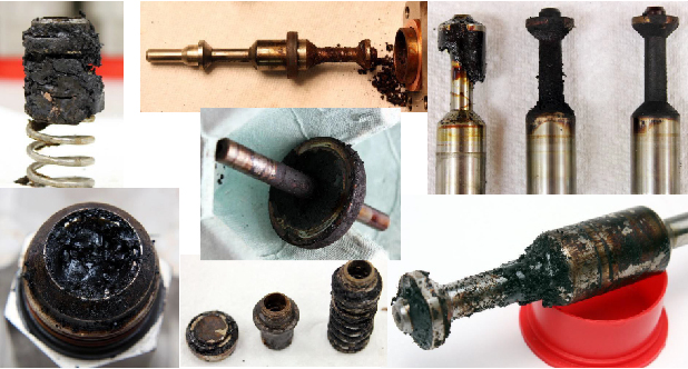
Gas Turbine Failure Modes Visualized
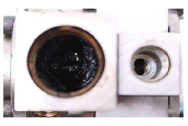
Fuel oil after exposure to high temperature as it transitions to solid coke
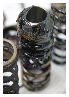
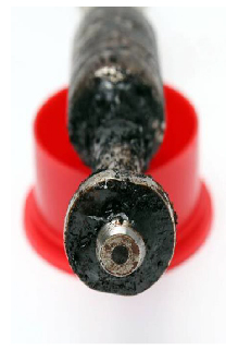
Viscous Fuel From Supply Lines Which Have Been Subjected to High Temperature
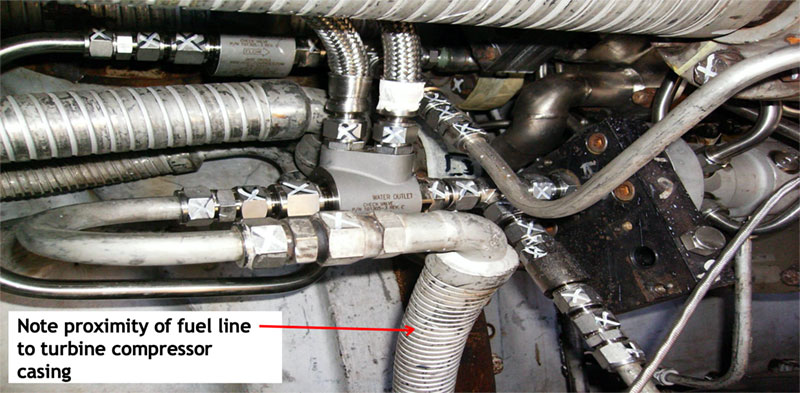
Water cooled 3-WPVs whose fuel supply lines were mounted next to turbine casings
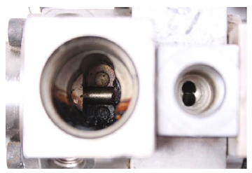
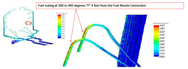
Why Coke Forms in Fuel Supply Lines
The tubing at the fuel nozzle is above the 300°F limit of fuel coking occurring. The goal is to keep all the tubing below 250°F.
Why do these temperatures matter?
Coke From Walls of Fuel Supply Lines Fouling Valves and Fuel Nozzle Passages
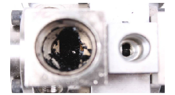

- Each time a turbine operates on liquid fuel another layer of residue, which will form coke, is deposited.
- Thermal Expansion/Contraction fuel supply lines or hydraulic hammer from Liquid Fuel Check Valves experiencing high-frequency oscillation dislodges sheets of this material.
- While check valves or other fuel controls mounted at the combustor previously mitigated how much of this material could reach fuel nozzle passages, more recent piping configurations devised to improve liquid fuel reliability provide an unrestricted path for contaminants to reach these critical orifices.
- Resultant exhaust temperature spreads after either a thermal or oscillation event may require a forced outage and fuel nozzle refurbishment in order to alleviate the condition. It isn’t known if this material is capable of dissolving when exposed to liquid fuel flow.
How Does JASC Hardware Help Achieve 32,000 Operational Hours Between Maintenance Intervals?
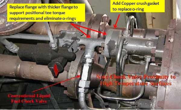
Water Cooled Components
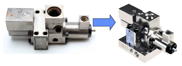
Check Valve Becomes Water-Cooled Check Valve

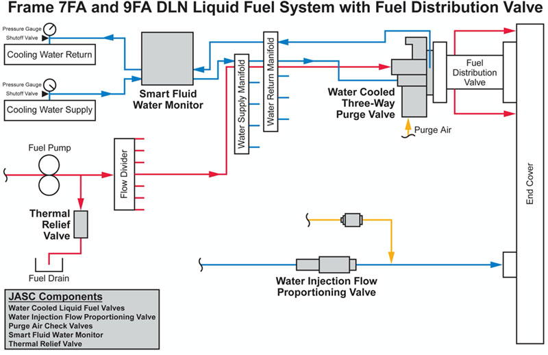
3-Way Purge Valve Becomes Water Cooled 3-Way Purge Valve
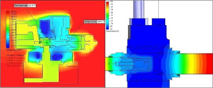
Coking Analysis
JASC has developed a line of water-cooled components that solve the coking problem.
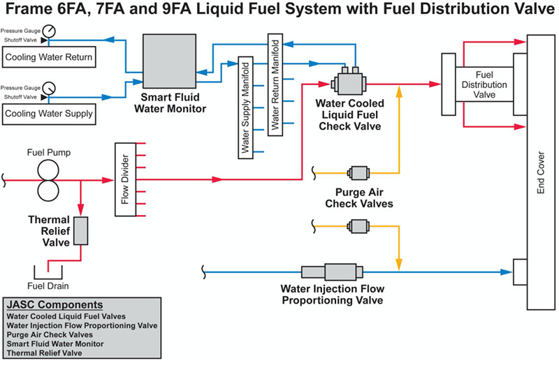
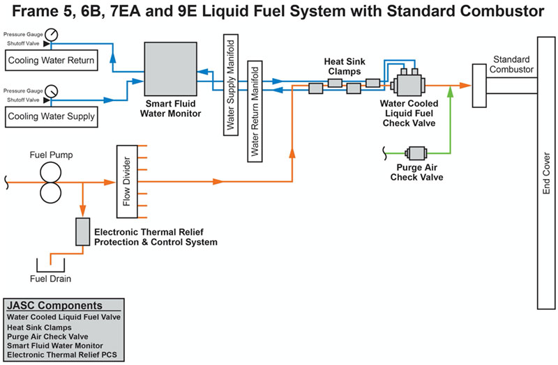
Water-cooled Liquid Fuel Check Valve System for Primary and Secondary Liquid Fuel
How Does JASC Hardware Help Achieve 32,000 Operational Hours Between Maintenance Intervals?
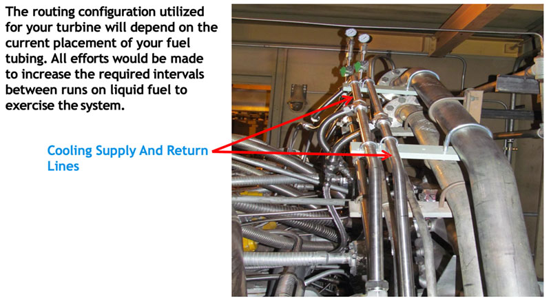
WCLFCV Installed on 7EA DLN Primary and Secondary Liquid Fuel System
Results: 5 years of monthly transfers with no trips
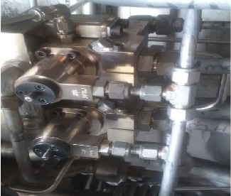
Water Cooled 3-Way Purge Valve System
Water Cooled Liquid Fuel Check Valve System
Dual Flange for Primary & Secondary Fuel Systems
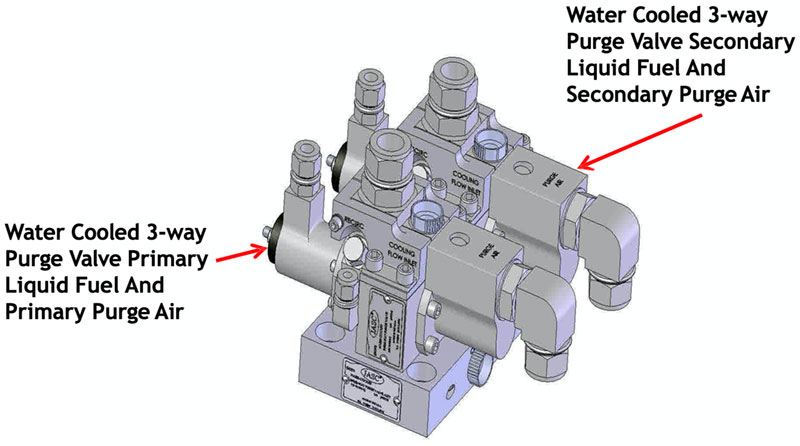
2013 Dual Flange Water Cooled 3way Purge Valve System
23 of 25 Successful Fast Starts on Liquid Fuel Prior to Valve Removal for C.I. in 2018
Zero valve failures during system operation with water.
Water Cooled Check Valve System With Heat-Sink Clamps
JASC Heat-Sink Clamps
Reduces Risk of Coking in Idle Liquid Fuel Lines Near Combustor Cans
The JASC Heatsink Clamp is designed to move heat away from idle liquid fuel lines by utilizing the adjacent coolant lines while the turbine is running on gaseous fuel.
With liquid fuel flow checked in close proximity to the combustor cans during operation on gaseous fuel, the liquid fuel can slowly cook down to a sludge, or worse yet, form carbon deposits, aka coke, on vital components of the liquid fuel system. When liquid fuel is needed, the sludge or carbon is introduced to the combustion nozzles, if anything flows at all.
If you have already taken advantage of JASC’s Water Cooled technology you know about the benefits of eliminating coking with our Three-Way Purge Valves and Liquid Fuel Check Valves. Now you can put the coolant lines to even better use.
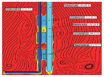
CFD analysis shows how effective active cooling can be. This example demonstrates the results when the coolant temperature is 120°F and the test oven set for 550°F. All temperatures in the simulated liquid fuel line are well below the coking temperature.
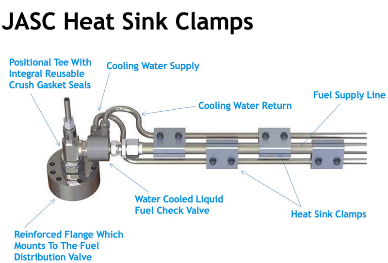
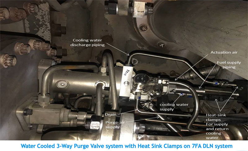
Water Cooled 3-WPV’s With Heat-Sink Clamps Installed
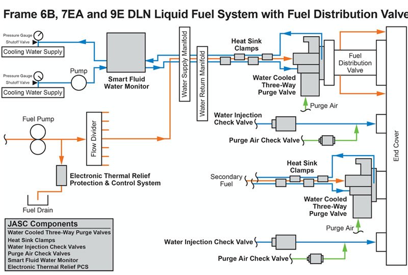
Water Cooled 3-WPV Installed on 7FA DLN System
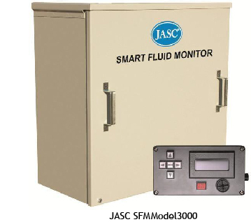
Thermal Relief Valve and Smart Fluid Monitor
JASC supporting technology which provides fuel nozzle protection from liquid fuel thermal expansion during turbine operation on natural gas and monitoring/protection for the valve cooling water system.
Smart Fluid Monitoring System
- Detects cooling system leaks and shuts off coolant flow, protecting turbine from potentially damaging water leaks.
- Regulates the coolant temperature to various cooled components on the turbine, such as check valves, 3-way purge valves, and flame detectors.
- Eliminates coking and waxing in fuel management components.
- Communicates monitored system parameters such as flow and temperature to the control room via remote-control unit.
- Uses fluid from the existing cooling system for economical installation and maintenance.
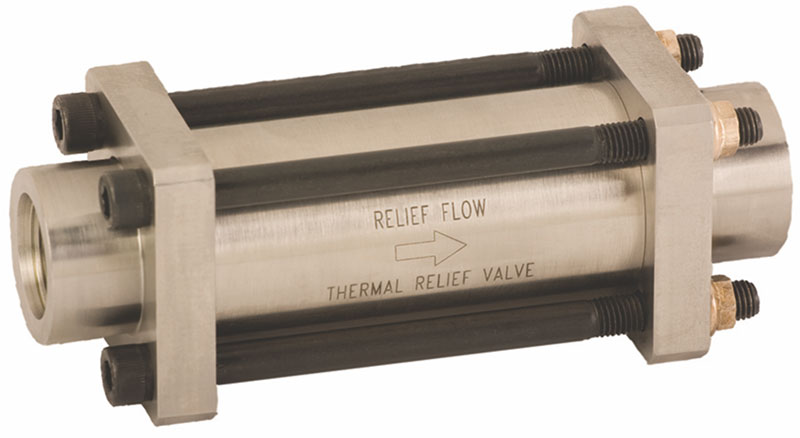
Thermal Relief Valve
Future Jasc Technology Which Provides Even Longer Intervals Between Runs on Natural Gas
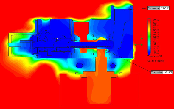
Water Cooled 3-Way Purge Valve With Internal Spool Cooling
Future Water Cooled 3-Way Purge Valve Design
CFD Analysis 95°F - Water Turned On
Gas Turbine Operational Goals
How Do We Achieve These Objectives?
- Utilize cooling water to keep both valve and fuel supply line temperatures low enough that viscosity changes which lead to coking and valve failure during gas operation doesn’t occur (Water Cooled Fuel Controls and Heat-Sink Clamps)
- Address structural integrity issues related to the ability to route fuel lines so that support from turbine casings is not required (Heat- Sink Clamps)
- Provide valve cooling water system monitoring/protection for detecting, annunciating, and stopping cooling water leaks (Smart Fluid Monitor)
- Provide thermal relief for liquid fuel so that expansion of stagnant fuel relieves in a designated location other than the fuel nozzle or through the check valve (Thermal Relief Valve)
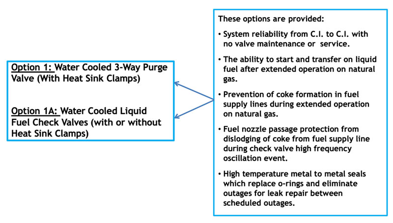
Suggested Liquid Fuel System Upgrade Options Based Upon Both Historical & Future Performance Improvement Capability
Contacts
David Hayward
President
(602) 438-4400 (ph)
(602) 438-4420 (fx)
dhayward@jasc-controls.com
Kevin Deutscher
Vice President
(602) 889-4154 (ph)
kevin@jasc-controls.com
Marla Evangelista
Sales and Marketing Manager
(602) 889-3715 (ph)
(602) 300-3703 (m)
(602) 438-4420 (fx)
marla@jasc-controls.com
Schuyler McElrath
JASC Consultant
Product Development / Technical Sales
(864) 350-4332 (ph)
schuyler@jasc-controls.com