JASC News
Reliable Liquid Fuel System

Correct component selection can overcome problems in the functioning of liquid fuel systems in dual-fuel gas turbines. Using the appropriate liquid fuel, purge air and water injection check valves will provide more than 95% availability and reliability — which is far better than the typical 35% – 40% in most dual-fuel applications.
Ensuring Fail Safe
Over the past 30 years, utilities have paid millions of dollars in additional cost when purchasing turbines that have dual-fuel capability or the ability to operate on both natural gas and liquid fuel. While a wide variety of devices have been tried over the years, until fairly recently, technology that addresses all of the primary causes of fuel system failures did not exist.
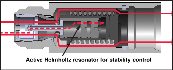
The liquid fuel check valve (Figure 1) is the first component that should be addressed when seeking to improve fuel system reliability. Two key characteristics of the design should be: A Helmholtz resonator and active cooling. These features address the most common failure modes that have been seen over the past couple of decades.
High-frequency oscillation or chatter in the check valve is the result of pulsations from the flow divider which excite the check valve when the resonant frequency of the check valve spring is reached. The reaction of the check valve can be extremely violent.
Hydraulic hammer associated with the rapid opening and closing of the check valve can actually cause the fuel tubing to break. The Helmholtz resonator attenuates the pressure signature of the flow divider output, eliminating the chatter and premature wear of the check valve internals which causes the loss sealing capability. While this design feature has been available for at least 10 years, the stability which ensued after its implementation created an ideal environment for another failure mode — coking.
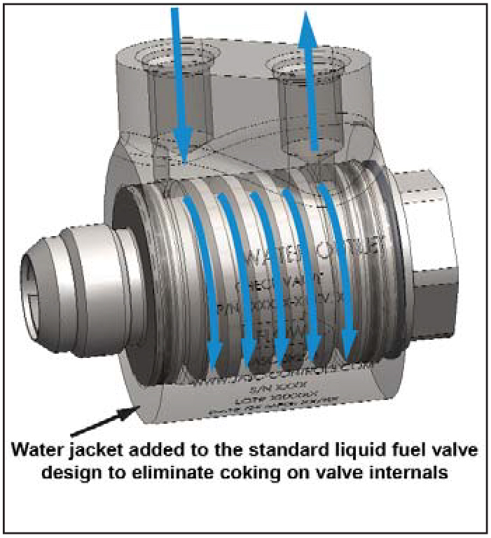
Active cooling (Figure 2) is the next key characteristic required for a liquid-fuel check valve design. Keeping the valve internals below the threshold, which allows the formation of coke, ensures that a Class 6 seal is maintained in the checked and reverse flow direction from hot gas path inspection to hot gas path inspection. The absence of coke formation also enhances the ability to start the turbine on liquid fuel and transfer back and forth between fuels because the check valves are able to maintain the same cracking pressures.
While this technology has only been available since 2005, it has accumulated over two million hours of successful operation in worldwide turbine applications. Specifically, turbines using this technology have demonstrated the ability to service these valves at hot gas path inspections.
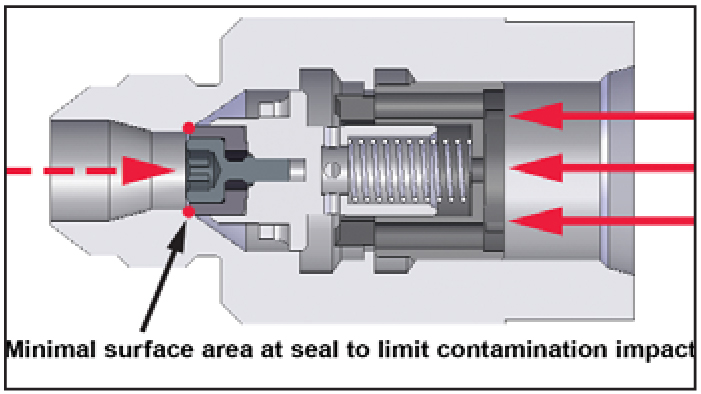
The purge air check valve (Figure 3) is the second component, which should
be addressed. The design should be contamination tolerant, chatter resistant and provide a Class 6 seal in the reverse flow direction. Given the low force margin (less than 1 psi) required for opening the valve, the check valve design should incorporate a knife edge seat to improve its tolerance to contamination.
The purge air check valve design should also provide a toggle action when opening and closing. This feature prevents the check valve from experiencing high frequency oscillation and premature wear of the valve internals. Vibration of the turbine during operation coupled with the low force of the purge air system also dictates that a toggle action design be used. The absence of wear due to chatter ensures that the valve will be capable of sealing against fuel oil in the reverse flow direction when the turbine is operating on liquid fuel.
The third and final component is the water injection check valve. It also has to be impervious to high-frequency oscillations, and capable of providing a Class 6 seal. Otherwise, the pressure signature of the positive displacement pump that supplies the water acts upon the resonant frequency of the valve spring and will cause premature wear of the valve internals when chattering occurs. Maintaining the Class 6 seal prevents the water system from evacuating during periods of inactivity. Consequently, when the water injection system is activated, all of the water lines will be full. This in turn will prevent exhaust temperature spreads that tend to trip the turbine.
In conclusion, implementation of water-cooled, liquid-fuel check valves, purge air check valves and water injection check valves can provide advantages for owners of dual-fuel gas turbines.
Author
 Schuyler McElrath, a GE veteran of 22 years, is a consultant for JASC: Jansen’s Aircraft Systems Controls. JASC specializes in the development of new technology for process control problems in industrial, aerospace and aviation applications. Reach McElrath at engineering@jasc-controls.com
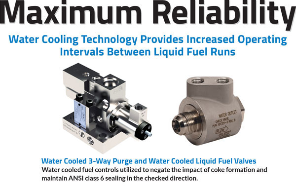
Experience Increased Operating Intervals Between Liquid Fuel Runs with JASC’s Water Cooling Technology
Abstract from CCJ Onsite Combined Cycle Journal – June 27, 2018:
Reliable operation of dual-fuel gas turbines on oil demands that owner/operators protect against coking of distillate in fuel-system components. Active cooling is one solution available to users for assuring both reliable starts on liquid fuel and reliable fuel transfers from gas to oil.
Recall that stagnant fuel in supply lines not protected against heat radiated from the gas-turbine casing transitions to solid coke over time. In earlier stages of the coking process a tar-like substance is created that fouls check valves, coats fuel-nozzle passages, and builds up on the inside surface of oil piping. Case in point: Key components of liquid-fuel systems on many dual-fuel 7FA gas turbines are located in a 500F environment, double the nominal 250F temperature at which coking of distillate begins.
JASC, Tempe, Ariz, has been at the forefront of industry efforts to improve the reliability of liquid fuel systems for well over a decade. The company’s subject-matter expert, Schuyler McElrath, told the editors, “Active cooling of the fuel supply system has been a fundamental component of our technology and has demonstrated the ability to improve reliability.”
JASC Products used for active cooling of the fuel supply include:
- JASC’s All-New Heatsink Clamps
- JASC’s Water-Cooled 3-Way Purge Valve
- JASC’s Water-Cooled Liquid Fuel Check Valve
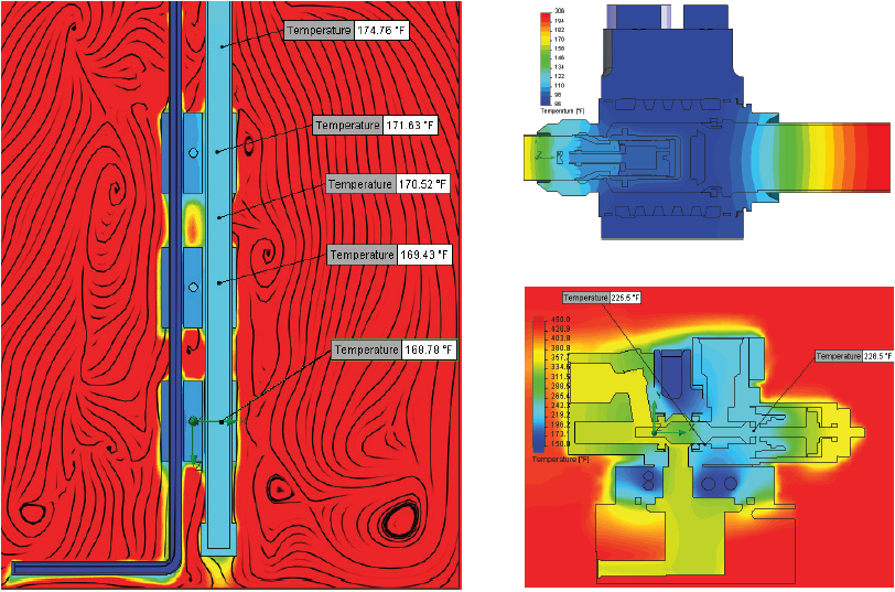
Thermal analysis shows the effectiveness of active cooling (Left: Fuel lines with heat-sink clamps installed, Top Right: Water-cooled liquid fuel check valve, and Lower Right: Water-cooled 3-way purge valve.)
JASC System Performance Examples
In one case, JASC Water Cooled Liquid Fuel Check Valves have operated on two 7F dual fuel machines for almost two years without issue. Operation on liquid fuel was only performed when required, not to exercise the system.
A second set of four DLN 7EA turbines outfitted with JASC Water Cooled 3-Way Purge Valves have operated since November of 2013 without a valve failure. While only one set of valves have been removed for service, due to a scheduled C.I., the turbine successfully performed 23 of 25 fast starts over this four year period. (Note: the customer insulated fuel piping on this application as Heatsink Clamps were invented in 2016).
Next, seven 7FA’s were upgraded to JASC Water Cooled 3-Way Purge Valves during 2017, with a total of six completed in December of 2017. Four of these turbines have accumulated in excess 7000 hours of operation on gas and approximately 300 hours of operation on liquid fuel over a three month period. A set of 14 valves removed from one of these turbines, for a C.I., were described by the customer as looking brand new. The difference in performance is profound. In a previous application, before the implementation of JASC Heatsink Clamps, six weeks of operation on natural gas was long enough to degrade stagnant liquid fuel to the point where its viscosity was the consistency of tar and attempts to burn fuel would result in high exhaust temperature spreads, flame out and exhaust temperature trips.
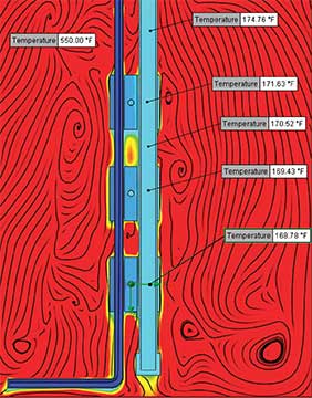
CFD analysis shows how effective active cooling can be. This example demonstrates the results when the coolant temperature is 120°F and the test oven set for 550°F. All temperatures in the simulated liquid fuel line are well below the coking temperature.
The limits of gas operation for JASC Heatsink Clamps has not been determined at this point. CFD data suggests that fuel should remain pristine over significantly long periods of time. Given that one of our latest installations will not run on liquid fuel unless called upon, we anticipate that our customer will run strictly on natural gas for the next six months of their summer season.
Liquid Fuel System Operational Capability: THE NEW REALITY
The new reality for gas turbine owners, as it relates to long term operational capability, is that a JASC solution has achieved another significant milestone in the industry. Specifically, while turbine owners have long enjoyed the benefits of a greatly improved liquid fuel system by replacing existing hardware with JASC designs, our latest product developments address another factor which is of critical importance, reduction of annual fuel costs.
In order to mitigate customer concerns about fuel costs associated with needing to regularly burn liquid fuel in the turbine in order to maintain reliability, JASC has developed and incorporated new hardware. The “thermal clamp” is the latest design to complement our comprehensive design philosophy. This device drastically reduces how often a turbine is required to burn diesel in order to maintain or verify component and system integrity. The thermal clamp is a very simple, elegant and inexpensive design that has proven to be a great addition to the JASC product line. While turbines typically need to run at least once a month, thermal clamps have drastically increased this interval. The resultant savings for fuel were approximately $330,000 for one 7F turbine over the course of one year, with no degradation of reliability.
Mouse over the image below to see details of a design configuration using JASC’s heat sink thermal clamps, purge air valve, swivel tee, flange, and water cooled liquid fuel check valve.
[heatsink]
In our first test of the thermal clamp, two peaking 7F turbines were outfitted with JASC’s complete design configuration. Thermal clamps, water cooled liquid fuel check valves, purge air check valves, positional tees, Smart Fluid Monitors, thermal relief valves and copper crush gaskets were all applied to this installation. The results after 15+ months of operation have been phenomenal.
These turbines, which were run on liquid fuel during system commissioning, have operated almost exclusively on natural gas since the upgrades were completed in April of 2016. The first run on liquid fuel occurred in January of 2017, fully nine months after the test run. Both turbines were operated without incident. The second documented run on liquid fuel occurred when scheduled emission tests were performed during the summer of 2017. Based on the information we received, a total of two liquid fuel runs occurred over a period of 15 months, with no loss of system integrity.
Finally, additional testing, which incorporates thermal clamps with JASC’s water cooled 3-way purge valves, is currently underway. Results should be available for publication in May of 2018. JASC expects to set new standards for reliability from this application as well. Thermal clamps’ ability to eliminate heat-related viscosity changes to stagnant diesel in fuel supply lines along with other innovative JASC designs add another level of performance to our system configurations. No maintenance or service until a major turbine service interval is reached, minimal need to exercise the liquid fuel system and significant reduction of fuel costs all provide for a better gas turbine owner experience relative to both reliability and cost.
Read More About the Benefits of JASC’s Thermal Clamps
Thermal clamps help prevent coking in gas turbine liquid-fuel lines
Thermal Clamps Help Prevent Coking in Gas Turbine Liquid-Fuel Lines
This article by JASC was recently featured in the Combined Cycle Journal, Number 53, Second Quarter. Read the article below or right click to download it here.
Reliable operation of dual-fuel gas turbines on oil demands that owner/operators protect against coking of oil in fuel-system valves and piping. Active cooling is one solution available to users for assuring both reliable starts on liquid fuel and reliable fuel transfers from gas to oil.
“Cool valves, piping improve engine reliability when called to burn oil,” CCJ 1Q/2016 (p 69) and available at www.ccj-online.com (type headline into the search-function box), discusses several cooling options offered by JASC. One of these, the so-called “thermal clamp,” was introduced as that article was in preparation.
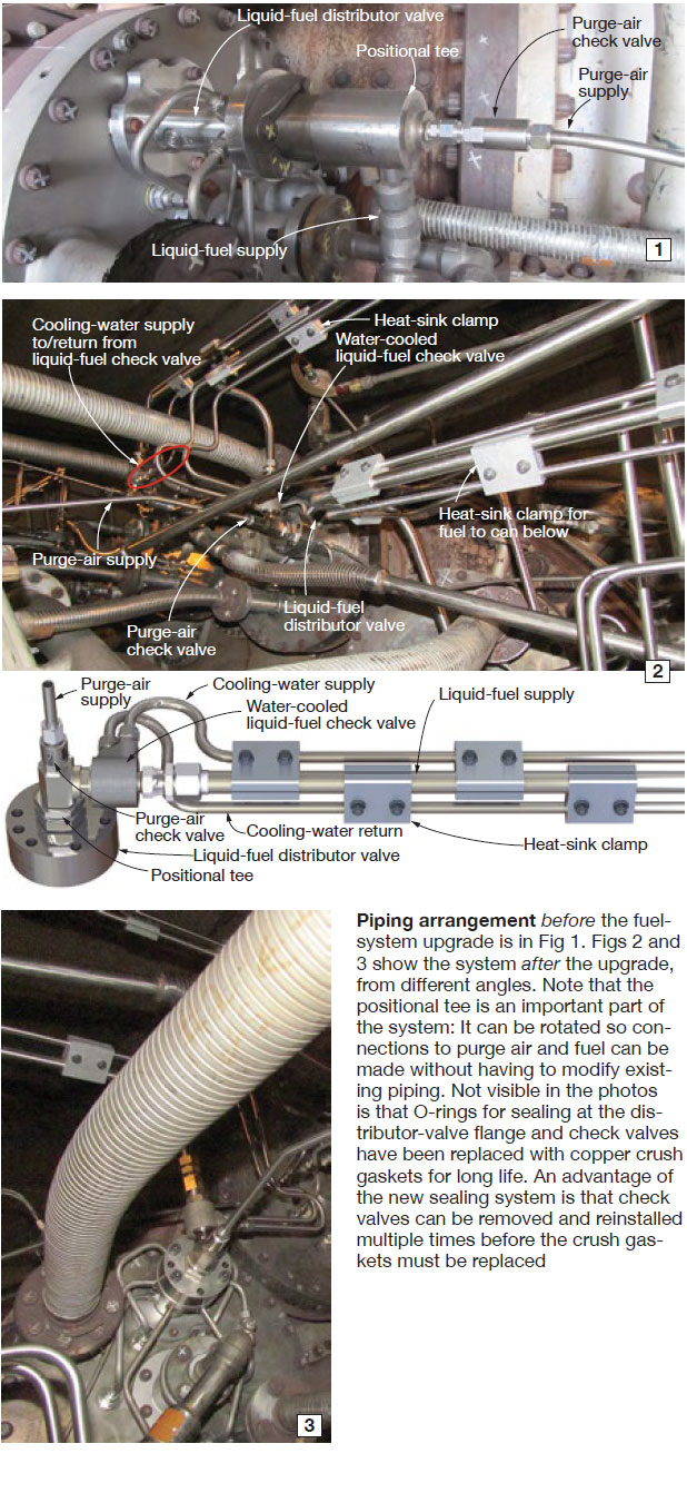
Early results available from the first commercial installation (Fig 1, before; Figs 2 and 3, after point to success both in protecting against coking and eliminating the need for “verification” firing of oil monthly to confirm liquid-fuel system reliability.
JASC’s (Tempe, Ariz) Schuyler McElrath told the editors, “With our latest system configuration consisting of rerouting fuel piping, incorporation of heat-sink clamps to keep fuel lines cool, water-cooled fuel controls, and component connections which don’t use O-rings, we are now offering the capability of running on liquid fuel at semi-annual intervals, or longer, without sacrificing back-up liquid-fuel system reliability.
“In the first test of this latest configuration, the second of two 7F gas turbines operated on liquid fuel during commissioning of the fuel-system upgrade in April 2016. The site operated exclusively on natural gas over the next nine months, burning oil only during the second week of January 2017. The next run on liquid fuel was in July 2017. Both times, the turbines started and operated on liquid fuel without incident.”
Thus the two-unit site burned liquid fuel successfully twice in the 15-month period ending in July. The typical site needing to confirm oil firing capability on two units would have paid approximately $60,000 each month the test was conducted. Thus, not having to run tests for 13 of the 15 months since the upgrade was completed saved more than three-quarters of a million dollars.
Based on this success, the owners of other sites currently are upgrading the fuel systems on some of their 7FA engines. These particular upgrades present a variation on the original concept in that they will be using JASC water-cooled 3-way purge valves to replace either standard 3-way purge valves or check-valve and purge-air valve configurations. Piping modifications highlighted here will be incorporated.