2020 News Archives
7F Users Group’s 2020 Digital Conference
One of the unique aspects of the 7F Users Group’s 2020 Digital Conference is the opportunity to interact online with the OEM and nearly 50 third-party solutions providers. Ten companies in the latter group were selected by the steering committee to conduct live technical presentations.
JASC was honored to be one of the selected presenters.
JASC’s Schuyler McElrath, presented about the complexity inherent in liquid fuel systems and on what design features owner/operators should be aware of to assure reliable starts on oil, reliable transfers from gas to oil, and vice versa, and reliable operation on both fuels. His presentation stressed that while some issues can be addressed with hardware upgrades, system infrastructure changes are an equally important part of the performance improvement process.
If you are a member of the Power Users Forum, you can view Schuyler’s presentation here.
Keeping Liquid-Fuel System Components Cool Improves Reliability of Transfers from Gas to Oil
![]()
This article originally appeared in the Third Quarter, 2009, Combined Cycle Journal Online.
The auxiliaries session of the May meeting included open discussion of experience with liquid-fuel systems for dual-fuel engines. Only a couple of years ago, some owner/operators were disabling or removing their liquid-fuel systems both because they weren’t being used and they added to the complexity and cost of annual inspections.
Recently, a few gas-only engines have been or are being converted to dual fuel because of grid-reliability concerns (example at www.combinedcyclejournal.com/archives.html, click 2Q/2009, click “Termocandelaria” on the issue cover).
Municipals and cooperatives, in particular, are specifying dual fuel for new units and improving the functionality of liquid fuel systems on existing gas turbines (GTs)—this to assure native load doesn’t go dark in the unlikely event gas supply is interrupted. Recall that public power companies are owned by their customers, most of whom are voters.
During the floor discussion, one user reported good success with the OEM’s liquid-fuel recirculation system in increasing the reliability of fuel transfer at various loads. Two other users reported positively on multiple plant experiences with water-cooled check valves installed to improve the functionality of their liquid-fuel systems. The valves, manufactured by JASC (Jansen’s Aircraft Systems Controls Inc, Tempe, Ariz) prevented coking of distillate which, at a minimum, impeded operation. In extreme cases, engines wouldn’t operate at all on oil.
The coking problem many users experience with standard liquid-fuel check valves occurs after switching from oil to gas. Oil remaining in check valves, which are located close to the combustor, is exposed to high temperatures. Above about 250F that oil is oxidized. The resulting coke coats check-valve internal surfaces (and fuel lines as well) and restricts the movement of valve parts. Once this occurs, a check valve will not open and close properly until it is overhauled. The most common trip during fuel transfer is on high exhaust-spread temperature—caused almost exclusively by check valves “hung-up” on coked fuel.
To get a first-hand look at the issues faced by users with dual-fuel GTs and the role played by JASC valves in solving some of those problems, the editors talked to one 7FA owner/operator and one 7EA user—the latter at the recent Fall Turbine Users Forum conducted by the Combustion Turbine Operations Task Force (CTOTF).
7FA Experience
Schuyler McElrath, JASC’s expert on fuel systems for large frame engines, told the editors at the vendor fair that Progress Energy Carolina’s Richmond County Energy Facility had more experience with the company’s water-cooled liquid-fuel check valves than any other generating plant. So COMBINED CYCLE Journal spoke with David Saad, O&R (operations and results) superintendent.
The station has five simple-cycle 7FAs and one 2 × 1 7FA-powered combined cycle. All engines are equipped for dual-fuel firing and have DLN2.6 combustion systems. Plus, all have JASC water-cooled liquid-fuel check valves—14 per GT (one per combustor). The first engine was equipped with the valves in 2006. When the 2 × 1 Siemens 501F-powered combined cycle is completed, the station will have a summer rating of about 1900 MW.
The peakers each start 100 to 200 times annually and run between about 1000 and 1500 hours. The combined-cycle is a mid-range unit. Unit run time on distillate ranges from about six to 25 hours annually today—virtually all of that to keep the liquid-fuel systems exercised. The few check-valve problems experienced, Saad said, were cooling-water related.
Water for valve cooling comes from the closed cooling-water system, which recirculates a mixture of water and glycol. The fin-fan cooler for the peakers supplies water at about 130F in summer; that for the combined cycle, about 150F. Such hot water for cooling is not problematic because the goal is to keep the check valves under 250F.
Saad recalled that fuel-transfer reliability was in the low 60s (percent) with standard check valves and the reason why the plant switched to JASC. Today transfer reliability is in the upper 80s. Saad cautioned that not all fuel-transfer failures are related to the check valves.
Installation was not difficult, he continued. Plant personnel prefabricated all the lines after the trial installation, which took about two days per unit. Staff also did the installation—typically a day for each engine. Early on, Saad added, they operated the check-valve cooling circuit with a delta P that was too high: 50 psi. Overcooling allowed unwanted wax to come out of solution. Reducing the differential pressure to 12 psi eliminated the issue.
Finally, Saad said, to assure that the plant maintains fuel-transfer reliability at a high level, check valves are removed each combustor and hot-gas-path inspection and returned to JASC for servicing. He does not want any failed fuel transfer attributed to a check-valve problem.
7EA Experience
Dave Hollandsworth, GT principal engineer for Gainesville Regional Utilities (GRU), walked the editors through his experiences with dual-fuel engines. It made War and Peace seem like a short story. GRU has several generating units, including a 235-MW coal-fired steam unit, but the Florida city’s DLN-1 equipped, dual-fuel 7EA is the sole focus here. Installed in 1996, it does 120-150 starts annually.
By way of background, Hollandsworth joined Gainesville in August 2002 after working for two major investor-owned utilities in the South. One of many items on his “to-do” list: Get the largest of the utility’s three gas turbines at the Deerhaven Generating Station (there are two Frame 5s in addition to the 7EA) operating reliably on distillate oil.
Water-cooled liquid-fuel check valves were one part of the solution, Hollandsworth told the editors, but only one part. However, the entire history of the engine is worth a quick read because it illustrates the importance of exercising standby fuel systems regularly if you expect them to perform properly when needed.
One of the first things the new hire did was to piece together an operational history for the engine. Here’s what he learned:
- Historically, the unit had operated on gas. Operation on gas was assumed satisfactory because Hollandsworth found no documentation to the contrary.
- Periodic operation on oil was confirmed by the need to replace leaking liquid-fuel check valves in December 1996.
- In fall 1998, the buildup of coke was sufficient to damage some crossfire tubes, which were repaired/replaced. Coking issues persisted and more crossfire tubes were replaced about six months later.
- A spate of operational problems traced to liquid fuel led to the replacement of check valves with the OEM’s newly designed three-way purge valves in fall 1999. Hollandsworth said the job report claimed proper operation through all load ranges on gas and oil, as well as successful fuel transfers.
- Discussions with operations personnel indicated that coking issues soon reappeared. Evidently, the unit would operate on gas for hours with distillate trapped in the liquid fuel system. Later attempts to run on oil would be unsuccessful. It appeared to Hollandsworth that the plant just gave up on liquid fuel at that point and ran on gas.
Fuel quality. The foregoing findings got Hollandsworth thinking about the quality of fuel in storage. Analysis revealed a stability rating of 15, indicating the fuel was unstable. Chemists told him a stability number above 7 is unsatisfactory. Fuel treatment brought the stability rating down to 2, but it just doesn’t stay there—especially in the heat and humidity of Florida. Semi-annual retesting was recommended, with follow-up treatment when necessary.
Additional tests were run on the “satisfactory” fuel to better understand its tolerance for heat. GRU engineers determined that GT compartment temperature can get as high as 300F and wanted to know how long it would take for the fuel to start forming particulates at that temperature. The answer: six hours. That meant any liquid fuel remaining in the system probably would begin to coke during the next run on natural gas.
Hollandsworth had joined the company just before the first hot-gas-path inspection in January 2003. One finding: Some secondary fuel-nozzle tubes were completely plugged with carbon deposits. During tuning after the HGP, engineers found some secondary liquid-fuel “pigtail” lines completely plugged with carbon.
Fuel lines and nozzles were cleaned in the spring and the plant began testing on liquid fuel again in June. No issues were encountered in the primary circuits, but the water injection system for the secondary circuits had problems—the most obvious was frozen flowmeters attributed to lack of exercise.
An inspection and rehabilitation plan was prepared for the water injection system, but work was postponed for more than a year because personnel were reassigned to address issues associated with forced and scheduled outages of the main coal-fired unit. The days of large unit-dedicated staffs are history. Today everyone works on everything.
Testing resumed on liquid fuel in June 2005, but a high temperature spread at 12 MW with only the primary nozzles in service tripped the unit. Liquid fuel sat in the pigtail lines for almost two years while the unit operated on gas. Hollandsworth said that, according to the Mark V timers, the 7EA had accumulated only seven hours of operation on liquid fuel since unit installation nine years earlier.
It was clear that proper operation of the liquid fuel system hinged on reducing the exposure time of oil to high heat or reducing the temperature of the oil, or a combination of both. One idea was to purge oil from the system (end cover to burner front) using nitrogen or atomizing air.
Problem with this approach was the risk of flame out on transfer from gas to oil under load because of empty fuel lines. In addition, there would still be some seals and o-rings in the three-way purge valves exposed to distillate and they would be prone to deterioration and gum-up by particulates.
Hollandsworth began discussions with JASC after speaking to McElrath at a user group meeting and came away thinking that water-cooled check valves were a viable solution. They would allow changing fuels under load while holding temperature below the threshold for particulate formation. Experience at other sites confirmed this.
GRU purchased the water-cooled check valves, purge-air check valves, tubing, and other components recommended by JASC to modify the liquid-fuel system during the combustor inspection planned for January 2008.
It’s important to recognize that the switch to the JASC solution was not a matter of just cutting out a few valves, welding in some new ones, and hooking up water supply and return lines. Also needed was OEM support to modify the Mark V controls from three-way purge-valve operation to water-cooled liquid-fuel check valve operation.
PAL Engineering, a unit of Pond And Lucier LLC, Clifton Park, NY, was retained as GRU’s technical advisor for the combustor inspection. Project Manager Carlo Barrera, mechanical TA and startup engineer, said this CI essentially was a modified HGP that took nearly eight weeks and included the following tasks:
- Convert from three-way purge valves to water-cooled check valves.
- Replace first-stage turbine nozzles, which exhibited severe cracking.
- Clean the fuel-oil system to assure as-new-as-possible condition prior to restart.
- Repair exhaust frame.
- Analyze turbine casing crack.
- Replace fuel nozzles.
Barrera said this was his first experience with the JASC solution. He rated the project “challenging,” primarily because of the controls-logic changes necessary, a different basket of plumbing hardware to deal with, prefab effort, fuel system cleaning, etc. Water for cooling the check valves comes off the closed cooling-water system (70% water, 30% glycol), which also supplies the lube-oil cooler and other auxiliaries—including the small heat exchanger that reduces the temperature of compressor discharge air for purge, atomizing, and fuel-nozzle cooling purposes.
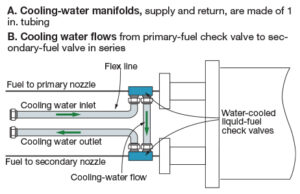
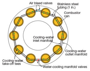
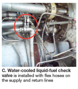
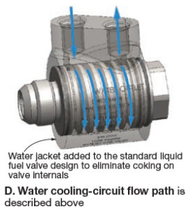
Hollandsworth added that 1-in.cooling-water supply and return manifolds were installed (Fig A) to serve all combustors in parallel. Fig B shows that cooling water flows to the primary fuel nozzle first and then to the secondary nozzle (in series). A water-cooled check valve, as installed, is in Fig C, with a drawing to illustrate how the valve works in Fig D.
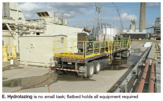
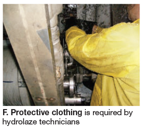
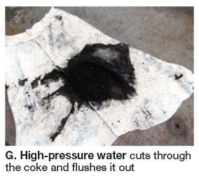
Cleaning of the fuel system required an effort that should not be underestimated, continued Hollandsworth. He said a holistic approach was used to make sure the job was done properly. Hydrolazing was used to cut through coke in fuel lines and remove it from the system. System clean-up took about a week. Truck with necessary equipment is in Fig E, worker protection required in Fig F. Process gets results: Coke removed is in Fig G.
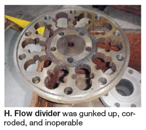
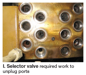
Among the problems identified: (1) The flow divider was gunked up, corroded, and inoperable (Fig H); it was replaced. (2) The selector valve was plugged (Fig I) and refurbished. (3) Purge-air solenoids for the secondary-fuel circuit were found inoperative.
All work complete, recommissioning of the liquid fuel system was reasonably straight-forward. The system has been exercised monthly for the last year and has met expectations. It also has participated successfully in alerts, which requires burning oil. GRU’s standard 30-min test: Unit is started on gas, switched to oil and run up to at least 60 MW, allowing check-out of the primary and secondary purge-air and water-injection systems. Then load is reduced and the unit transferred back to natural gas for shutdown. After shutdown, atomizing air and check-valve cooling water continue to run for eight hours.
Replace Two Types Of Check Valves And Your Backup Liquid Fuel System Can Operate At Better Than 95% Availability And Reliability

This article originally appeared in the July 2009, Modern Power Systems Turbine Technology Directory.
Utilizing the appropriate liquid fuel and purge air check valves will provide a level of operational capability which can exceed 95% availability and reliability; a number far better than the typical 35 to 40% foremost dual fuel applications. More importantly, these modifications can yield the same outstanding results no matter the age or size of the turbine.
Over the past 30 years, utilities have paid millions of dollars in additional cost when purchasing turbines which have dual fuel capability or the ability to operate on both natural gas and liquid fuel. A comprehensive solution was only developed relatively recently.
 The liquid fuel check valve is the first component which should be addressed when seeking to improve fuel system reliability. Two key characteristics of the design should be passive dampening and active cooling. These features address the most common failure modes which have been seen over the past couple of decades. High-frequency oscillation or chatter in the check valve is the result of pulsations from the flow divider which excite the check valve when the resonant frequency of the check valve spring is reached. The reaction of the check valve can be extremely violent. Hydraulic hammer associated with the rapid opening and closing of the check valve can actually cause the fuel tubing to break. The passive dampening feature attenuates the pressure signature of the flow divider output, eliminating the chatter and premature wear of the check valve internals which causes the loss of sealing capability. While this design feature has been available for at least 10 years, the stability which ensued after its implementation created an ideal environment for another failure mode: coking.
 Active cooling is the next key characteristic which is required for a liquid fuel check valve design. Keeping the valve internals below the threshold which allows the formation of coke ensures that a Class 6 seal is maintained in the checked and reverse flow direction from hot gas path inspection to hot gas path inspection. The absence of coke formation also enhances the ability to start the turbine on liquid fuel and to transfer back and forth between fuels because the check valves are able to maintain the same cracking pressures. While this technology has only been available since 2005, it has accumulated over two million hours of successful operation in
worldwide turbine applications. Specifically, turbines utilizing this technology have demonstrated the ability to service these valves at hot gas path inspections.
The purge air check valve is the second component which should be addressed. The design should be contamination tolerant, chatter resistant and provide a Class 6 seal in the reverse flow direction. Given the low force margin which is required for opening the valve, less than 1 psi, the check valve design should incorporate a knife edge seat to improve its tolerance to contamination. The purge air check valve design should also provide a toggle action when opening and closing. This feature prevents the check valve from experiencing high frequency oscillation and premature wear of the valve internals. Vibration of the turbine during operation coupled with the low force of the purge air system also dictates that a toggle action design be used. The absence of wear due to chatter ensures that the valve will be capable of sealing against fuel oil in the reverse flow direction when the turbine is operating on liquid fuel.
In conclusion, implementation of water-cooled liquid fuel check valves and purge air check valves can provide tremendous advantages for dual fuel gas turbines of any age. As gas turbine designs have a wide variety of configurations for the liquid fuel, purge air and water injection systems, we recommend that you contact JASC for details on how these designs can be used to benefit your specific application.
Real-World Test Validates Concept

This article originally appeared in the October 2007, Diesel & Gas Turbine Worldwide.
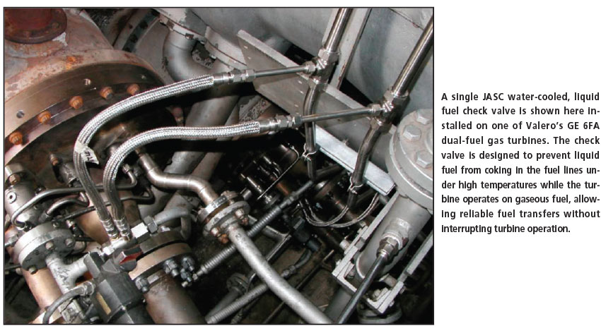
With the availability of reliable, quality, electric power using gaseous or liquid fuel paramount, a Valero petrochemical facility in Delaware City, Delaware, U.S.A., recently worked with Jansen’s Aircraft Systems Controls Inc. to upgrade two of its dual-fuel, gas turbines in an electric power generation application to improve equipment reliability during fuel changeover.
At the facility, Valero was experiencing trips that ultimately led to turbine shutdown episodes during operator attempts to switch from gaseous to liquid fuel or liquid to gaseous fuel during turbine operation. Not only did these unplanned shutdowns cost money, this situation can also be damaging to the equipment.
“The start/stop cycle thermal transition is hard on a turbine, and the severity of this cycle is usually intensified because the unplanned trip happens under full power — making it exceptionally hard on the turbine components,” said Schuyler V. McElrath, a spokesman for JASC. “A trip under load is almost always worse than that of a trip under a start-up, or just stopping and starting a turbine under normal conditions.”
After troubleshooting the equipment, maintenance engineers determined that the trips were caused by liquid fuel coking within the liquid fuel lines and check valves of the turbine, thus creating blockages during extended runs on gaseous fuel. This coking was caused by excessive temperatures transferred to the stagnant liquid fuel contained within the supply lines and check valves. The problem prevented the turbine operators from consistently switching from gas to liquid fuel reliably on the fly.
In order to accomplish the fuel changeover, operators were required to shut
down the turbines, perform service checks and any needed cleaning of the fuel system components before restarting the turbines on the gaseous fuel and then making the switch to liquid fuel. This situation limited the flexibility of the equipment and made operational planning very important.
To combat the problem, Tempe, Arizona, U.S.A.-based Jansen’s Aircraft
Systems Controls Inc. (JASC) struck a deal with Valero to install six of its
newly introduced water-cooled liquid fuel check valves (WCLFCV), one per can, on one of the facility’s two GE, 6FA dual-fuel gas turbines.
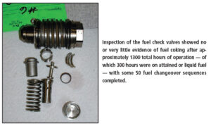
For the test, the turbines were run for approximately 1300 total hours — of which 300 hours were on liquid fuel — and conducted some 50 fuel changeover sequences during turbine operation. At the end of the test, the valves were removed and returned to JASC for inspection.
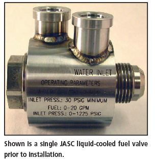
According to the JASC service report, all six valves were received after use,
visually inspected and photographically recorded. Some of the units showed what JASC referred to as minor discoloration at the fuel inlet and discharge ports, but all were completely free of fuel coking residue. The cooling water inlet and outlet ports of some valves also showed some slight discoloration that appeared to be caused by the heterogeneous mixture of water and carbon-based particles. There appeared to be no extended damage and all the units were determined to be functional.
 In malfunctioning check valves, when two or more valves fail to seal due to coke or contamination, combustion gas migration through the fuel system heats check valves to 538° or 649°C. Consequently, check valve internal components need to be able to withstand high temperatures, this characteristic offers significant protection for the fuel nozzles. The fuel nozzle orifices, which are very small, can become clogged if material inside the check valve melts and migrates downstream. “The water-cooled check valve keeps the temperature of the liquid fuel inside the check valve well below the coking threshold of 250°F (121°C),” said McElrath. “Keeping the fuel cool prevents the coking from occurring and subsequently allows the check valve to maintain its functionality for very long periods of time.”
After the visual inspection was complete, all valves were tested to JASC’s production acceptance procedure. All units passed the tests and all internal
leakages in the check direction were bubble tight. These results, according to JASC, represent a milestone for liquid fuel check valves in operation on a dualfuel engine for 1300 hours. Heretofore, coking after approximately 100 hours was significant enough to cause check direction leakage and less than desired operation in the flow direction.
After the testing procedure, all six valves were subjected to a teardown
and further visual checks. During these inspections, there was no coke formation and only light discoloration of static parts observed. All the sliding surfaces were found to be completely free of coke and varnish.
In addition, the water-cooled check valves were found to still maintain class
6 seal, preventing backflow of gas in the system. This translates into reliable
liquid fuel starting and prevents large temperature spreads, therefore preventing trips, according to McElrath.
If the stop valve has leakage problems, in extreme cases, pressurization can
occur all the way back to the main fuel storage tank and the transfer can produce catastrophic results, including the destruction of fuel pumps and other system components along with fuel system supply pipes. This pressure spike usually cracks the check valves. They are designed to operate at 8 to 10 bar and the spikes can be as high as 83 bar due to the
capabilities of the fuel pump. Other problems include multiple check valves that will not close, resulting in fuel pressure at the cans not being distributed equally.
“Users usually do not attempt a fuel transfer on the fly,” said McElrath. “They want to avoid the problems and potential trips.”
According to the JASC report, the incorporation of the WCLFCV’s on the Valero turbine, by itself, improved operational reliability of the engine system by approximately 40%.
Transfer from gas fuel to liquid fuel for IGCC applications shows low reliability rates, especially for liquid-cooled applications with a dual-fuel configuration no matter the turbine manufacturer, according to McElrath. While gas-only operation is in the 95% reliable range, the switch to liquid fuel on a dual-fuel application has a low reliability level, in some cases as low as 35% according to JASC.
Since this initial test, Valero elected to have additional valves installed on
the remaining gas turbine in the fleet at this facility. With these valves installed, the application reliability level for fuel switchover has been boosted to the 95% or better range on dual-fuel applications, according to JASC.
“This is a range at which the operator feels comfortable to do the fuel transfer without experiencing a trip,” said McElrath. “In the past, they would shut down the turbines, check the fuel systems and then restart them on liquid. A similar strategy is employed when the switch was made back to gaseous fuel.”
 As of recently, the JASC valves at the Valero site have over 300 starts on distillate fuels and more than 200 transfers. More importantly, according to
McElrath, “Valero has also set new industry standards by successfully operating their turbines for intervals of more than 8000 hours without experiencing check valve problems.” According to JASC, the WCLFCVs can be installed on GE gas turbine frame sizes of 5, 6B, 7EA, 7FA, 6FA and 9E. JASC also has valves that are being developed for testing on Siemens equipment.
Liquid Fuel Check Valves Improve Reliability on Gas Turbine Engines
![]()
This article originally appeared in the Second Quarter, 2010, Combined Cycle Journal Online.
Will your dual-fuel gas turbine (GT) start on distillate the next time you hit the button? Will your engine transfer to oil from gas without tripping offline the next time you switch fuels?
Good questions that many operations personnel would like to answer with a positive “yes,” but can’t. There are several reasons why plants often experience poor reliability on liquid-fuel starts and on fuel transfers, including these:
- Ineffective procedures for assuring high availability of the liquid-fuel system. Diligent maintenance and regular “exercise” of all system components are particularly important.
- Inadequate training of O&M personnel. Liquid-fuel systems cannot be an afterthought; they command respect.
- Off-spec fuel, either through purchase or deterioration in storage.
- Coking of oil in piping and valves located close to hot engine parts.
- Check valves do not reseat properly.
First three items are well within the plant’s control. A solid dose of commitment is all that’s needed in most cases. The last two also are within the plant’s control—at least for facilities equipped with dual-fuel GE Frame 6, 7, and 9 DLN engines (including F class)—but they require a small investment either in new hardware or modification of existing equipment.
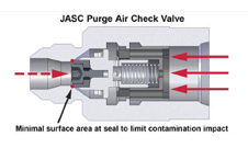
You may recall that the first liquid-fuel systems for dual-fuel DLN engines had separate valves for fuel and purge air (Fig 1). Also, that purge air is supplied continuously when the turbine is operating on gas; it is turned off when operating on oil.
Liquid-fuel check valves are prone to coking because of their close proximity to the engines served. Simply put, the light fractions in the small amount of oil that remains in the valve when the unit transfers to gas distills off, leaving a carbonaceous residue which could impede valve operation on ensuing starts and fuel transfers. Residue accumulates with each start and fuel transfer, often preventing proper seating of the check valve when oil firing ends.
When this occurs, purge air and combustion gases can travel all the way back through the oil piping to the flow divider, and beyond, causing fuel system evacuation, corrosion of the flow divider, and other issues. Units experiencing this condition are prone to tripping on the next attempt (1) to start on liquid fuel or (2) to transfer from gas to liquid fuel (no fuel in the line connecting the flow divider to the check valve).
One of the steps undertaken by the OEM to improve the reliability of its dual-fuel DLN frames was to combine the functions of the liquid-fuel and purge-air check valves into one valve body. Today, the three-way purge valve (3WPV) is standard equipment on DLN-equipped Frame 6, 7, and 9 engines (Fig 2). About 5000 of the valves, made by Jansen’s Aircraft Systems Controls Inc (JASC), Tempe, Ariz, are installed worldwide.
Scores of GTs still are equipped with individual liquid-fuel and purge-air valves and most would benefit from conversion to the 3WPV. However, there’s no stampede, according to Schuyler McElrath, because problems associated with distillate firing have caused many engine owner/operators to just give up on oil. Even the 3WPV is subject to coking problems.
By way of background, McElrath spent nearly 25 years working on fuel systems for the OEM before starting his own company, SMTC Inc, Greenville, SC. He spends much of his time helping users solve liquid-fuel problems on behalf of JASC.
Recognizing the paralyzing effect coking was having on GTs, JASC President Harvey Jansen, a pioneer in high-tech fluid-flow solutions for the aerospace industry, went “all-in” on the company’s ability to develop a “cool” liquid-fuel check valve.
Nearly four years ago, following successful beta tests at a refinery, the company began offering a water-cooled version of the liquid-fuel check valve (WCLFCV). These GE-approved valves now are installed on more than 100 engines worldwide. McElrath reports virtual 100% reliability on starts and fuel transfers.
The next logical step was to develop a water-cooled three-way purge valve (WC3WPV), shown integrated into the liquid-fuel system in Fig 3. A WC3WPV was required because GT owners using this technology needed an inexpensive way to achieve liquid fuel system reliability.
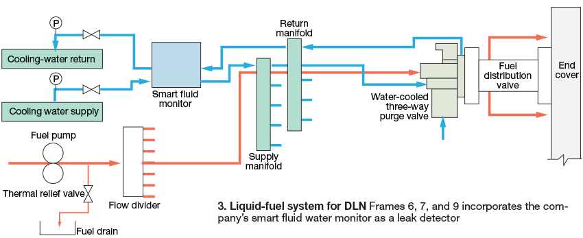
Piece of cake considering the company’s proven success with the WCLFCV. But Jansen, who epotimizes the iconic American technology/business leaders Thomas A Edison and Edwin Land (Polaroid), was concerned more about cost than simply designing a water-cooled valve.
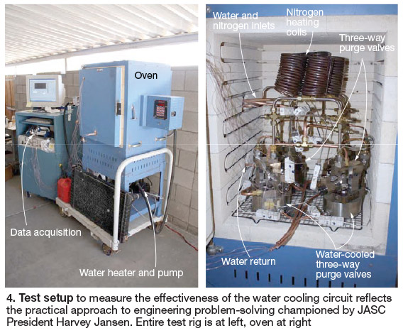
JASC engineers responded with a method for converting existing 3WPVs to water-cooled valves for about one-third the cost of a new valve. Next step was to run validation tests in the lab. The test rig was similar to that used for proof-of-concept tests on the WCLFCV (Fig 4). Photo shows that two uncooled and two water-cooled valves were tested simultaneously.
McElrath called in early August to say that the test results detailed in the “Design Verification Test Report” prepared by Project Engineer Kirby Meyer had been accepted by Jansen at the end of July and they proved that the valve was ready for commercial application. The WC3WPV is scheduled for installation on operating engines this fall.
JASC has a rotable pool of valves to swap out with existing 3WPVs—one or two per combustor for a GE frame, depending on the model being upgraded. McElrath says that the valves can be changed out and the water supply and return circuits installed over a weekend.
By contrast, it typically takes about two weeks to convert a turbine outfitted with 3WPVs back to a configuration which uses check valves. The extensive changes that must be made to purge-air and fuel piping are labor intensive.
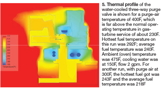
Lab tests were conducted in an environment far more challenging than the one that exists in a GT package and the results exceeded expectations, McElrath said. For example, the thermal profile of a WC3WPV in Fig 5 reflects purge air at 400F, well above the normal operating service temperature of about 230F.
Note that the purge “air” for testing purposes in the first phase of the testing program actually was nitrogen heated in the coils located at the top of the furnace (right side of Fig 4).
This was done to mitigate any safety concerns associated with a mixture of air and fuel at the auto ignition threshold of diesel oil.
Highest fuel temperature on this run was 292F, the average fuel temperature 240F. The threshold for coke formation is 250F. Regarding the fuel, slightly more than half an ounce (specifically, 20 cc) of No. 2 oil was injected into each of the four valves. Oil was added daily to replenish fuel that had distilled off and was safely vented.
Another test with purge air at 300F, still 70 deg F over normal operating temperature, revealed an average fuel temperature at only 218F. For both runs, the oven temperature was 475F, cooling water 150F (flow rate, 2 gpm).
The test program had two major parts:
- A two-day trial with extensive data collection, followed by trending of the data to assure that the test rig would produce the information required to validate (or not) the design of the water-cooled valve.
- A two-week test with about 80 hours of active oven time to assess coking tendency. For this test segment, nitrogen simulation of purge air was shut off and oven temperature increased to 550F to induce as much coking as possible. The two WC3WPVs were monitored continuously to ensure that valve temperature did not exceed 250F. Average temperature of the valves’ spool sections during the two-week run was about 220F.
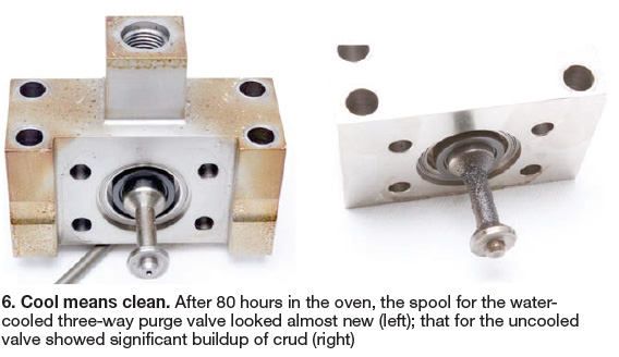
Over the two-week period, about 6 cc of distillate was added daily to replenish the two 3WPVs, compared to only 1 cc for the water-cooled valves. Consequently, considerable fouling was observed on the spools for the standard valves (right photo in Fig 6); the spools for the water-cooled valves were clean by comparison (left-hand photo).
Finally, regarding tightness of WC3WPV shutoff, expectations were surpassed. Better than an ANSI Class VI seal was achieved. More specifically, the WC3WPV spool seal was bubble-tight using 300-psig nitrogen.
To dig deeper into the details of the validation test program for the WC3WPV, access www.jasc-controls.com.