
2014 News Archives
Harv Remembered by CCJ Online
CCJOnline.com recently posted this thoughtful piece about Harv.
Harvey Byron Jansen was as much a star in the engineering world as members of the Brazilian World Cup team are in soccer. He, too, came to be known by his first name. If you said “Harv” to many of those knowledgeable about servos, actuators, valves, and combustion systems in aerospace and land-based gas-turbine applications, they knew immediately you were referring to the smart, effervescent guy in the lab coat with a resemblance to Dr Emmett Brown of Back to the Futurefame.
Harv was CEO of Tempe-based Jansen’s Aircraft Systems Controls, known to most readers by the acronym JASC. He founded the company in 1990 and over the next 24 years built a firm with an exemplary reputation for innovation and high-quality engineered flow-control products. He was 76 when he succumbed to cancer on the fifth of July, but mentally still in the prime of his professional career. Many would be inclined to say, “He will be missed.” For Harv, that trite phrase would be a gross understatement.
The editors visited JASC on several occasions over the years. The first time we were overwhelmed by all the disassembled products Harv had spread out on the conference room table. Like most power engineers, we were comfortable talking about large gate and globe valves for water and steam service that give the appearance of having been manufactured by a blacksmith. JASC products were at the other end of the spectrum, what precision parts for an artificial heart might look like.
7EA Experience with Water Cooled Liquid Fuel Check Valves Installed in Dual Fuel Engines
Source: Combined Cycle Journal, Third Quarter 2009
Site
Gainesville Regional Utilities (GRU)
Personnel Quoted: Dave Hollandsworth, GT Principal Engineer
Case Highlights
Prior to installation, the plant had given up on liquid fuel due to issues with coking.
After installation of JASC water cooled liquid fuel check valves and associated hardware, the system was exercised monthly for a year and met expectations. It also has participated successfully in alerts, which requires burning oil.
Background
GRU has several generating units, including a 235-MW coal-fired steam unit, but the Florida city’s DLN-1 equipped, dual-fuel 7EA is the sole focus in this case study. Installed in 1996, it performs 120 -150 starts annually.
Hollandsworth joined Gainesville in August 2002 after working for two major investor-owned utilities in the South. One of many items on his “to-do” list: Get the largest of the utility’s three gas turbines (there are two Frame 5s in addition to the 7EA) at the Deerhaven Generating Station operating reliably on distillate oil.
One of the first things Hollandsworth did was to piece together an operational history for the engine. Here’s what he learned:
- Historically, the unit had operated on gas. Operation on gas was assumed satisfactory because Hollandsworth found no documentation to the contrary.
- Periodic operation on oil was confirmed by the need to replace leaking liquid-fuel check valves in December 1996.
- In fall 1998, the buildup of coke was sufficient to damage some crossfire tubes, which were repaired/replaced. Coking issues persisted and more crossfire tubes were replaced about six months later.
- A spate of operational problems traced to liquid fuel led to the replacement of check valves with the OEM’s newly designed three-way purge valves in fall 1999. Hollandsworth said the job report claimed proper operation through all load ranges on gas and oil, as well as successful fuel transfers.
Discussions with operations personnel indicated that coking issues soon reappeared. Evidently, the unit would operate on gas for hours with distillate trapped in the liquid fuel system. Later attempts to run on oil would be unsuccessful. It appeared to Hollandsworth that the plant just gave up on liquid fuel at that point and ran on gas.
The foregoing findings got Hollandsworth thinking about the quality of fuel in storage.
Analysis revealed a stability rating of 15, indicating the fuel was unstable. Chemists told him a stability number above 7 is unsatisfactory. Fuel treatment brought the stability rating down to 2, but it just doesn’t stay there— especially in the heat and humidity of Florida. Semi-annual retesting was recommended, with follow-up treatment when necessary.
Additional tests were run on the “satisfactory” fuel to better understand its tolerance for heat. GRU engineers determined that GT compartment temperature can get as high as 300F and wanted to know how long it would take for the fuel to start forming particulates at that temperature. The answer: six hours. That meant any liquid fuel remaining in the system probably would begin to coke during the next run on natural gas.
Hollandsworth had joined the company before the first hot-gas-path inspection in January 2003. One finding: Some secondary fuel-nozzle tubes were completely plugged with carbon deposits. During tuning after the HGP, engineers found some secondary liquid-fuel “pigtail” lines completely plugged with carbon. Fuel lines and nozzles were cleaned in the spring and the plant began testing on liquid fuel again in June. No issues were encountered in the primary circuits, but the water injection system for the secondary circuits had problems—the most obvious was frozen flowmeters attributed to lack of exercise.
An inspection and rehabilitation plan was prepared for the water injection system, but work was postponed for more than a year because personnel were reassigned to address issues associated with forced and scheduled outages of the main coal-fired unit.
Testing resumed on liquid fuel in June 2005, but a high temperature spread at 12 MW with only the primary nozzles in service tripped the unit. Liquid fuel sat in the pigtail lines for almost two years while the unit operated on gas. Hollandsworth said that according to the Mark V timers the 7EA had accumulated only seven hours of operation on liquid fuel since unit installation nine years earlier.
It was clear that proper operation of the liquid fuel system hinged on reducing the exposure time of oil to high heat or reducing the temperature of the oil, or a combination of both.
One idea was to purge oil from the system (end cover to burner front) using nitrogen or atomizing air.
The problem with this approach was the risk of flame out on transfer from gas to oil under load because of empty fuel lines. In addition, there would still be some seals and o-rings in the three-way purge valves exposed to distillate and they would be prone to deterioration and gum-up by particulates.
Hollandsworth began discussions with JASC after speaking to Schuyler McElrath, JASC’s expert on fuel systems for large frame engines, at a user group meeting and came away thinking that water-cooled check valves were a viable solution. They would allow changing fuels under load while holding temperature below the threshold for particulate formation. Experience at other sites confirmed this.
Conversion Process
GRU purchased the water-cooled check valves, purge-air check valves, tubing, and other components recommended by JASC to modify the liquid-fuel system during the combustor inspection planned for January 2008.
It’s important to recognize that the switch to the JASC solution was not a matter of just cutting out a few valves, welding in some new ones, and hooking up water supply and return lines. Also needed was OEM support to modify the Mark V controls from three-way purge-valve operation to water-cooled liquid-fuel check valve operation.
PAL Engineering, a unit of Pond And Lucier LLC, Clifton Park, NY, was retained as GRU’s technical advisor for the combustor inspection. Project Manager Carlo Barrera, mechanical TA and startup engineer, said this CI essentially was a modified HGP that took nearly eight weeks and included the following tasks:
- Convert from three-way purge valves to water-cooled check valves.
- Replace first-stage turbine nozzles, which exhibited severe cracking.
- Clean the fuel-oil system to assure as-new-as-possible condition prior to restart.
- Repair exhaust frame.
- Analyze turbine casing crack.
- Replace fuel nozzles.
Barrera said this was his first experience with the JASC solution. He rated the project “challenging,” primarily because of the controls-logic changes necessary, a different basket of plumbing hardware to deal with, prefab effort, fuel system cleaning, etc.
Installation
Water for cooling the check valves comes off the closed cooling-water system (70% water, 30% glycol), which also supplies the lube-oil cooler and other auxiliaries—including the small heat exchanger that reduces the temperature of compressor discharge air for purge, atomizing, and fuel-nozzle cooling purposes.
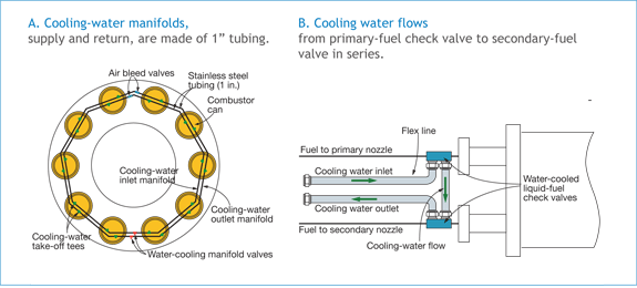
One inch cooling-water supply and return manifolds were installed (Fig A) to serve all combustors in parallel. Fig B shows that cooling water flows to the primary fuel nozzle first and then to the secondary nozzle (in series).
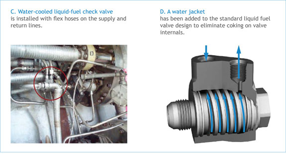
A water-cooled check valve, as installed, is in Fig C, with a drawing to illustrate how the valve works in Fig D.
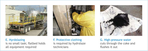
Cleaning of the fuel system required an effort that should not be underestimated, continued Hollandsworth. He said a holistic approach was used to make sure the job was done properly. Hydrolazing was used to cut through coke in fuel lines and remove it from the system. System clean-up took about a week. Truck with necessary equipment is in Fig E, worker protection required in Fig F. Process gets results: Coke removed is in Fig G.
Among the problems identified:
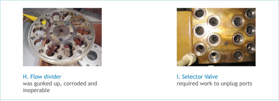
- The flow divider was gunked up, corroded, and inoperable (Fig H); it was replaced.
- The selector valve was plugged (Fig I) and refurbished.
- Purge-air solenoids for the secondary-fuel circuit were found inoperative.
All work complete, recommissioning of the liquid fuel system was reasonably straight-forward. The system has been exercised monthly for the last year and has met expectations. It also has participated successfully in alerts, which requires burning oil.
GRU’s standard 30-min test: Unit is started on gas, switched to oil and run up to at least 60 MW, allowing check-out of the primary and secondary purge-air and water-injection systems. Then load is reduced and the unit transferred back to natural gas for shutdown. After shutdown, atomizing air and check-valve cooling water continue to run for eight hours.
7FA Case Study: Upgrading to Water Cooled Liquid Fuel Check Valves
Source: Combined Cycle Journal, Third Quarter 2009
Site
Progress Energy, Carolina’s Richmond County Energy Facility
Personnel Quoted: David Saad, O&R (operations and results) superintendent
Case Highlights
- Transfer reliability is in the upper 80s (percent) after installation
- Installations typically took one day per engine
- The first engine was equipped with the valves in 2006
Background
The station has five simple-cycle 7FAs and one 2 × 1 7FA-powered combined cycle. All engines are equipped for dual-fuel firing and have DLN2.6 combustion systems. When the 2 × 1 Siemens 501F-powered combined cycle is completed, the station will have a summer rating of about 1900 MW.
The peakers each start 100 to 200 times annually and run between about 1000 and 1500 hours. The combined-cycle is a mid-range unit. Unit run time on distillate ranges from about six to 25 hours annually—virtually all of that to keep the liquid-fuel systems exercised.
7FA Engine Performance Before Converting System Hardware to Improve Reliability
Saad recalled that fuel-transfer reliability was in the low 60s (percent) with standard check valves and the reason why the plant switched to JASC.
7FA Engine Performance After Converting System Hardware
Today transfer reliability is in the upper 80s (percent). The O&R Superintendent cautioned that not all fuel-transfer failures are related to the check valves.
Conversion Process
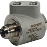
JASC’s Water Cooled Liquid Fuel Check Valve incorporates active cooling of the check valves internals while maintaining a Class 6 seal in the check and reverse flow direction from hot gas path to hot gas path.
The O&R superintendent classified the process as “not difficult.”
Plant personnel prefabricated all the lines after the trial installation, which took about two days per unit. Staff also did the installation— typically a day for each engine. Early on, Saad added, they operated the check-valve cooling circuit with a delta P that was too high: 50 psi. Overcooling allowed unwanted wax to come out of solution. Reducing the differential pressure to 12 psi eliminated the issue.
To assure that the plant maintains fuel-transfer reliability at a high level, and to avoid any failed fuel transfers being attributed to check valve problems, the check valves are removed from each combustor and hot-gas-path inspection and returned to JASC for servicing.
Installation
All engines have JASC water-cooled liquid-fuel check valves—14 per GT (one per combustor). The first engine was equipped with the valves in 2006.
Water for valve cooling comes from the closed cooling-water system, which recirculates a mixture of water and glycol. The fin-fan cooler for the peakers supplies water at about 130F in summer; and for the combined cycle at about 150F. Such hot water for cooling is not problematic because the goal is to keep the check valves under 250F.
According to the O&R superintendent, the few check-valve problems experienced were cooling-water related.
Valves & Actuators: The Path to Greater Efficiency & Performance
JASC was featured in Power Engineering’s April 2014 publication, discussing innovative applications and design modifications that have lead to improvements in actuator technology, reducing costs and providing better performance for high-pressure steam bypass, turbine bypass, and other critical power plant operations.
Read JASC’s contribution to the article below.
Over time, there may not be another auxiliary system more maligned than that of a back-up liquid fuel system on a dual fuel gas turbine. The hardware shortcomings responsible for the inability to start on liquid fuel or transfer from gas to liquid fuel, check valve failures, flow divider failures, fuel system evacuation, exhaust temperature spreads, and related turbine trips have all been addressed by designs developed by JASC Controls. Water cooled check valves, which prevent carbonization, metal to metal sealed water injection check valves rated for service at 750 degrees “F”, multiple use crush gasket technology which replace o-rings with a 1000 degree “F” rating at 2000 psi and a Zero Emissions Equipment design which allows a turbine owner to test the readiness of the liquid fuel system without firing on oil are examples of the JASC’s unique technology.
These system specific products have two common design goals. First, they provide reliable operation for at least 32,000 hours or until a scheduled turbine service interval is reached. This provides the optimal timing for returning the valves to the JASC facility for refurbishment after three or four years of use.
Second, the valves must maintain an ANSI Class 6 sealing capability from installation until removal for refurbishment. Elimination of reverse flow results in separation between the turbine combustion process and auxiliary systems such as liquid fuel, purge air, and water injection. With no reverse flow of combustion gasses into these systems, back-up fuel system availability and reliability typically exceed 98 percent.
Finally, JASC’s solutions are configured to be interchangeable with the turbines existing hardware. This characteristic both minimizes the cost and reduces the time associated with performing fuel system upgrades on a turbine of any age.